MULTI-ELEMENT PHASED ANTENNA ARRAYS FOR GROUND
AND AIRBORNE APPLICATIONS
-
Michael Parnes - Ascor Co., St.Petersburg ascor@parnes.spb.ru
-
http://www.ascor.eltech.ru
-
-
Raphael Shifman - Resonans Co, St.Petersburg shifman@resonance.spb.ru
-
Tel/Fax No: (7-812) 553-8445
-
-
-
Abstract
| This paper discusses problems of economical and technological expediency
evaluation in application of
electronically scanned phased arrays for different
applications |
In order to receive a signal from a few satellites, it is customary
to use an electromechanically scanned parabolic antenna that has many disadvantages,
among them those connected with its poor environmental resistance. A planar
antenna is, contrastingly, more resistant to environmental influences such
as wind, rain, snow, etc. In addition, it can easier be mounted at the
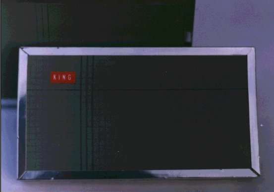
top of building. Therefore, it has since 1986 been suggested that an in-phase
planar array[1] antenna containing no phase shifters be used for this purpose
(Fig.1).
 Fig.1
The Matsushita Co. (Japan) has been among leading developers/sellers of
such antennas for application to DBS television since 1987. In April 1987
their phased arrays have been purchased for the broadcast reception through
the BSB satellite in the United Kingdom and then - for the TV SAT in Germany.
Fig.1
The Matsushita Co. (Japan) has been among leading developers/sellers of
such antennas for application to DBS television since 1987. In April 1987
their phased arrays have been purchased for the broadcast reception through
the BSB satellite in the United Kingdom and then - for the TV SAT in Germany.
The phased array technology itself allows several controlled phase
shifters to be installed at the same time as radiators, i.e. solder-mounted
on the same printed-circuit board, which increases the cost of antenna,
though. For this reason, it is of vital importance for a mass user, as
opposed to a military one, to assess wherein lies a novel phased array
functionality and what is the price for that complication.
It can be seen from the analysis that the phased array containing
12 phase shifters may commercially be of interest since it makes possible
reception of TV broadcasting within the angular coverage 8° in Western
Europe. This sector, in particular, covers the area from ASTRA 1A-1B (19,2°
East) to TELECOM 1C (3° East) (Fig.2).
 Fig. 2
Table 1. gives comparison of different phased array versions.
Table 1
|
Number of
Phase Shifters
|
Angular Coverage,
+/- deg.
|
Gain, dB
(normally to
the surface)
|
Gain, dB
(at the edge of
sector)
|
Frequency,
GHz
|
|
12
|
8
|
34.5
|
32
|
10.9-11.7
|
|
12
|
8
|
35.5
|
33
|
11.7-12.75
|
|
24
|
16
|
33.5
|
31
|
10.9-11.7
|
|
24
|
16
|
34.5
|
32
|
11.7-12.75
|
|
48
|
60
|
34.5
|
30
|
10.9-11.7
|
A phased array containing 24 phase shifters is also a promising option
covering the sector +/- 16° , e.g. from EUTELSAT 2-F1 (13° East) to TVSAT
2 (19° West). Such a phased array antenna can carry out reception from
nine DBSs in the territory of Western Europe.
To phase the beam, p-i-n diode phase shifters should be mounted on
the 65 x 3 cm printed-circuit board(Fig.3).
 Fig. 3
The p-i-n diode phase shifter is controllable through a three-digit
code and best compatible with the in-tuner available digital control unit.
An essential difference of the planar phased array from the electromechanically
scanned parabola is its very short beam switching time, a few microseconds
in duration. Such a high beam transport velocity permits the use of the
phased array in vehicle based DBS systems (airborne, shipborne, automotive,
etc.).
Described technology can be used for other ground based and airborne
applications where we need signal reception from different directions.
Together with LNA-s this technology can be used for warning collision radars,
ground and satellite communications in frequency range from 1-80 GHz. Typical
measured power radiation pattern (RP) of our multi-element microstrip array
at 37 GHz (Fig 4a) is shown in Fig. 4b.
 (a)
(a)
 (b)
Fig. 4
We used elements of this technology for multi-element focal MMIC array
at 26-30 GHz for RATAN-600 radio telescope [2].
(b)
Fig. 4
We used elements of this technology for multi-element focal MMIC array
at 26-30 GHz for RATAN-600 radio telescope [2].
Conclusion
The DBS television development analysis indicates that the number of satellites
will be growing year after year, just generating a need for reception
of signals from different directions using the same antenna. The phased
array antenna that uses a printed-circuit board as a radiating curtain
and p-i-n diode based microstrip phase shifters appear to have considerable
promise for meeting the challenge. A phase shifter of that sort is fully
compatible with the tuner processor and will be cost-effective in mass
production.
The phased array use will permit user-friendly modes of operation, such
as automatic search of satellites followed by memorizing their coordinates
in order to switch over to the desired satellite within microseconds.
The phased array antenna is characterized by its inherent high speed of
beam switching and this enables one to use it in DBS systems to be installed
on movable objects such as coaches, trucks and ships.
Described technology can be used for different ground based and airborne
applications as well.
References
1. M.D.Parnes.Experience of the Automated designing of patch antenna
arrays. Ship-building industry(USSR), issue 19, 1989.
2. V.Khaikin, E.Majorova,R.Shifman, M.Parnes, V.Dobrov, V.Guzevich.
MMIC Solution for Multi-pixel Reception in RATAN-600 Aberrational Focal
Zone. Proceed. of 2-nd ESA Workshop on Millimetre Wave Technology and Applications,
Espoo, Finland, 1998.