Report at URSI/IEE Convention on Radio
Science,
Multi-beam Solar Radio
Telescope of Tuorla Observatory :
test operations
V.Khaikin*, S.Yakovlev**,
A.Kazarinov**,
I.Efimov***, A.Volkov***, E.Valtaoja*****
*The Special Astrophysical
Observatory of RAS,
357147, N.Arkhyz,
E-mail:
** BUM TECHNO JSC,
Nevsky pr.65, PO BOX 217,
191025, St.Petersburg,
E-mail:bumt@bumt.spb.ru
***The
195251 Polytechnicheskaya
29,
**** Tuorla
Observatory UTU,
FIN-21500 PIIKKIO,
E-mail:esko.valtaoja@utu.fi
1.Introduction
Multi-beam
Solar Radio Telescope (MSRT) of Tuorla Observatory is intended for patrol Solar observations in the band of 3-10 mm. Solar
flux and Solar flare monitoring are among main MSRT tasks with the aim of further enhancing the links
between ground-based and satellite observations of the Sun.
Low
resolution moment images of the Sun at 3 mm (36 pixels) and a differential beam
method at 10 mm may be useful for
diagnostics of pre-flare and flare process and detection of very weak variations
of Solar flux caused by instability of magnetic field structure in active
regions before flares [1].
MSRT
project was developed in cooperation with NRTT Lab (The
Special Astrophysical Observatory/St.Petersburg State
Technical University) in 2000, MSRT
status at Autumn 2002 is given bellow.
2.MSRT dish
A
2 m precise carbon fiber parabolic dish was developed and fabricated for MSRT at "Luch Co" in
The
main design features are:
1.A 3 layer honeycomb structure is used
in the solid dish design.
2.Additional external metallic
strengthening beams of the back structure provide support against expected wind
loads in open air conditions without a protecting radome.
3.Four metallic struts connected with beams of the back structure support the secondary
mirror and a focal array. The 2 m parabolic
dish has the ability to withstand wind speed not less than 40 m/sect.
4.A special
anti-corrosion layer was
applied to protect the metalized dish surface
from the atmospheric effects in open air
conditions. A special
surface cover also
protects MSRT receivers from the heating due to the Sun.
5.Relation of outer and inner
foci of the hyperbolic secondary mirror is f3/f2=1.5 that increases an
effective radio telescope focal
distance, reduces spacing of neighboring
beams and off-axis aberrations in
a multi-beam case.

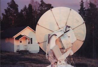
Fig.1. The 2 m precise carbon fiber parabolic dish: front(left) and
back (right) view.
MSRT
characteristics are given in table 1.
Table 1
|
Location |
Latitude:
60° 24'57", Longitude: 22° 26'42"E, Altitude: 53 m a.s.l. |
|
|
Type/mount |
Cassegrain / Equatorial |
|
|
F/D |
0.425 |
|
|
Illumination angle from the Secondary focus,
deg |
100 |
|
|
Main
dish diameter/weight, m/kg |
2/74 |
|
|
RMS
surface error, μm |
85 |
|
|
Drives |
Step-motors N1 and N2 with
gearboxes, AC motor N3 with gear-box |
|
|
Control System |
PCB with serial PC port,
encoders with ISA PC interface |
|
|
Pointing
speed α/δ, arcdeg per sec |
1/0.1 |
|
|
Sun tracking
time, summer/winter, hr |
-+6 / +4 |
|
|
Tracking error
(max), arcmin |
+-1 |
|
|
Frequency
range, MM |
10 |
3* |
|
HPBW,
arcmin |
17.5’ |
5’* |
|
Number
of beams |
2- 6* |
25*-36* |
|
MMIC
receiver sensitivity in wide channel per beam per sec, mK |
50 |
100* |
|
Polarization |
Circular (L/R) |
Circular (L/R) |
|
Stocs parameters |
I,
V |
I,
V |
|
Time resolution, ms |
1 |
1 |
|
Aperture efficiency |
0.7 |
0.6* |
* - expected
3.Results of
measurements
1.A surface error mapmeasured with the
use of a contact 3D coordinate
measurement gear has 85 micron RMS deviations of the best fit (Fig.2, left).


Fig 2. MSRT dish surface map,
RMS error 85 microns (left),
testing of the MSRT
dish in
2.A
tuning of adjusting elements at 8 dish
supporting beams of a back structure
was necessary in working conditions to provide
a 100 micron standard
deviation at the
periphery of a parabolic
dish. A carbon fiber material is
sufficiently plastic to remove, if necessary, deviations of the best
fit in the range +-0.5 mm.
A laser theodolite
of AXYZ STM/MTM industrial measurement system (Leica Geosystems) was used for this procedure. A method to adjust
up to 10 m precise carbon fiber compound dish in working conditions with RMS accuracy up to 20 microns was developed
and tested as well (Fig.3) [3].


Fig. 3. Results
of measurements of the parabolic dish under test. Positions of measurement
points (top, left), isolines with the step 0.1 mm
(top, right), the needle in different projections (bottom, left, right).
3.MSRT polar axis and nulls of encoders
were fixed by a laser theodolite in the absolute
coordinate system with accuracy 15”. Positions of the secondary
mirror and focus were preliminary fixed as well but will be specified later on
results of antenna and geodesic measurements.
4.MSRT radiation patterns at 10 mm for an
off-axis feed measured on ground-based oscillator in the near (0.1*D**2/λ)
and Fresnel zone (0.98*D**2/ λ) are close to
expected(Fig.4) but show that some correction of secondary dish position is
necessary.

Fig.4. MSRT radiation patterns at 10 mm with (bottom) and
without (top) secondary mirror for an
off-axis feed measured on ground-based oscillator in the near(left) and Fresnel(right) zone
4.MSRT receivers
The
current status:
1.Two array receiver modules at 10 mm of
circular polarization(L/R)[4] are presently under test at MSRT(Fig 5 top).
Noise road and noise spectrum of a receiver module are given in Fig.6.
2.2x3
or 3x3 element focal receiver arrays may be then assembled of these modules as
well (Fig.5 bottom)
3.MMIC
technology may be also used to build array receiver modules at 3 mm but if we need 36 or more
pixels for Solar flare monitoring with
MSRT the mm-wave microbolometer
array technology developed by Metorex Oy, Finland [6] seems to be
more promising..


Fig.5.
Two array receiver modules at 10 mm of circular polarization(L/R)
without (top, left) and with thermostatic
Box (top, right), array from
receiver modules (bottom)