Expected
Characteristics of Multibeam Solar Radio Telescope with a Focal Focal Plane Microbolometer
Array at 100 GHz
V.Khaikin*, (1), A.Luukanen**(2),(3)
*(1)The Special
Astrophysical Observatory of RAS
195251, St.Petersburg,
Russia,
Polytechnicheskaya 21, of.107
E-mail:
(2)**Metorex Oy,
(3)Present Address: VTT
Information Technology, Microsensing,
E-mail:arttu.luukanen.vtt.fi
Abstract
Achievable parameters (NEP,NETD, dynamic range) of a focal plane array with room temperature microbolometers are
calculated in the range of 100-150 GHz. Expected characteristics of 8 m MSRT with a focal plane array at 100 GHz are given. Possible 2D array architecture is presented. For 8 m MSRT 15x15 element focal plane array is to be optimal at 100 GHz as well as 23x23 element focal plane array is near optimum at 150 GHz.
Keywords: Microbolometer,
focal plane array, multibeam radio
telescope.
1.INTRODUCTION
Multibeam receiver
system for Solar MM-wave burst observations was initially developed in 1989 for Itapetinga 13.7 m radio
telescope to study angular positions of Solar bursts [1]. The multipixel Sun
image has been a challenge
in MM band but it can be very useful for Solar
flare monitoring.
The
current status of Multibeam Solar Radio Telescope (MSRT) of Tuorla Oobservatory is given in [21]. 2
m precise MSRT dish is suitable for Solar flare monitoring at 100 GHz where up to 6x6 pixels may be obtained in
Sun disk area. For MSRT
with bigger dish (up to up to 8 m) more than 20x20 pixel Sun images may be
available at
100-150 GHz. New electroformed Nickel panel technology developed by Media Lario Co. [32] gives us a chance to adopt light but very precise sandwich type panels for bigger MSRT dish with Cassegrain optics suitable for thea multibeam moderadio
telescope.
Modern MMIC technology was
applied for MSRT receiver array at 10 mm30 . GHz.
Characteristics of array receiver
modules are given in [43]. Two MMIC array receiver modules at 26-30 GHz10 mm of circular polarization(L/R) are
presently under test at MSRT. 2x3 or 3x3
element focal receiver arrays may be then assembled withof these modules. MMIC technology may be also also used to build array receiver
modules at 3 mm but ifwhen we need dozens or
hundreds 36 pixels for
Solar flare monitoring with 8 m MSRT at 3 mm the or more pixels for Solar flare monitoring with MSRT anantenna coupled microbolometer array array technology [64] developed by Metorex Oy, Finland seems to be
more promising for a focal plane
array.
2.MICROBOLOMETER ARRAY
2.1.Noise and
sensitivity of a room temperature
microbolometer
Our calculations
show that electrical noise
equivalent power (NEP)
10 pW/rtHz 10^-12 W/sqrt(Hz)
is achievable the nearest yearstoday
at 100-150
GHz for
an antenna
coupled microbolometer in operated at room
temperature. Noise equivalent temperature difference (NETD) is given by:
![]()
Where ε is the coupling efficiency, ∆F-bandwidth, τ-integration time. For a realistic
ε ~0.3, ∆F=45 GHz, τ=1 sec NETD=27 K for Ti-air bridge microbolometer. The use of new composite materials for microbolometer air-bridge with a lower 1/f noise gives us a chance to reach 10 K/sec in the nearest years. Estimated temperature sensitivity is less than the traditionally used to investigate quiet Sun or active Solar regions in MM band but it is quite permissible for Solar flare
monitoring with 8 m MSRT where antenna temperature can easily exceed 500-1000 K
above quiet Sun level in the Solar flare case. Wide dynamic range of a multibeam receiver system is more important parameter in our case.
2.2.Dynamic range of a microbolometer array
The dynamic
range of a microbolometer
in the array is determined mainly by the
resistance uniformity of the array and the read-out
electronics and to less degree by the microbolometers themselves. We can estimate the
dynamic range of the microbolometer by
noting that with 1 s integration time the minimal detectable power is 10 pW,
while the bias dissipation is about 0.2 mW. Saturation will take place when
optical power ~0.5 Pbias~100 mW, and thus
dynamic range = 100E-6/1E-11=1E7=70 dB. If we take the resistance variations from bolometer to
bolometer to be ~10 % (pessimistic), this corresponds at 1 mA bias
current to a signal voltage variation of about 20 mV. The
bolometer noise level is about 1 nV/sqrt(Hz), so the 1 s dynamic range
requirement for the read-out circuit is
20 mV/1e-9=2E7. Low noise
preamplifier, such as the Burr-brown INA103 has an input noise of 1 nV/sqrt(Hz)
at 1 kHz and maximum output is
10 V. The signal to the preamplifier will be chopped at 1 kHz, so the noise
bandwidth is 1 kHz. Thus, the limit for 1
kHz dynamic
range of the preamplifier is ~3E8. The required second gain
stage is capable of this dynamic range
too. In the end, the A/D
conversion will finally yield
the system dynamic range. The digitization noise from the least significant bit (lsb) is 1/2/sqrt(3)=0.3
lsb rms. Thus a 16 –bit A/D converter
for
10 % resistance
nonuniformity allows us to
realize noise NETD up to 10 K per 1 sec in 30% band.
2.3.Microbolometer array architecture
conditions that allows us
to realize in 30% band noise equivalent
temperature difference (NETD) up to 10 K per 1 sec. A lithographic log-spiral with one circular or dual circular (L/R) polarization may be applied as a microbolometer antenna in a widebandthis case. The Nb metal (Nb or Ti) air-bridge microbolometer is placed in the insert connecting spiral
arms.
Mentioned temperature
sensitivity is less than it is
traditionally needed to investigate quiet Sun or active Solar
regions but it is quite permissible
for Solar flare monitoring when MSRT antenna
temperature can easily exceed 500-1000 K above quiet
Sun level at 3 mm in Solar flare
case. Necessary
dynamic range more than 50 dB is reachable in a microbolometer array.
To reduce 1/f
noise an optical modulation of the entire array at ~1 kHz is needed. A rotating chopper with an archimedes’ spiral
shape is required to circumvent the large 1/f noise of the bolometers below 1 kHz-100 Hz. The optical coupling elements, i.e. the substrate lenses may be necessary to avoid 30 % signal loss at the Si-Air interface.
Possible 2D architecture and the design of microbolometer focal plane array for MSRT are given in Fig.1-2.
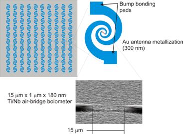
Fig.1. Possible 2D
architecture of microbolometer focal plane
array for MSRT
2D topology of 30x30 element microbolometer array at 100 GHz for MSRT is proposed. Expected MSRT characteristics with such a focal array are considered. Results of multibeam simulation at 100 GHz for 8 m primary
dish in the optimal Cassegrain case are presented.

Fig.2. Possible design of the focal
plane microbolometer array for MSRT
3.
CHARACTERISTICS OF MSRT WITH THE FOCAL
PLANE ARRAY AT 100 GHZ
3.1.Simulation
MSRT is able to work with 60% antenna efficiency at 100 GHz and single pixel microbolometer tests may be done today at 100 GHz or even at 150 GHz. If Media
Lario Co. panels are applied for bigger radio telescope MSRT dish may be completely smooth up to 300 GHz. So off-axis aberrations and gain losses for peripheral array elements are the most important. If gain loss for peripheral array
elements does not exceed -1.5 dB flux sensitivity of 8 m MSRT with a microbolometer focal plane array should not be worse than 1 s.f.u./per beam/per sec.
For double
reflector simulation we used GRASP8-SE software packages in

Fig3. Radiation
patterns of 8 m MSRT for on/off axis
feed of circular polarization (L/R) at 100 GHz with step λ/2.

Fig.4.Gain, HPBW,
first sidelobe level (FSL) and beam deviation (BD) as function
of feed removal from the focus.
Calculated
gain, HPBW, first sidelobe level (FSL) and beam deviation (BD) as function of removal from the focus
are presented in Fig.4 for a feed of linear polarization. Isolines of radiation patterns (Peak-3dB and Peak-30 dB) for on/off axis array feed are given in Fig.5.

Fig.5. Isolines of
radiation patterns at 100 GHz, peak-3dB(left) and peak-30 dB(right) for on(top)and off (bottom) axis array
feed
3.2.Optimization
of the focal plane array
To reach maximum number of independent pixels and minimum aberration level spacing of
array element must be close to
λ/2 in air. The use of a dielectric substrate with higher ε can reduce size of antenna element in
sqrt(ε) but it also adds mismatch and insert loss. The dipole, patch or spiral type antennas have the smallest size and is almost free from spillover
effects when they are well isolated. However an attempt to achieve a closely
packed multi-element system will reduce the sensitivity of each pixel due to "crosstalk" or mutual coupling[5]. Antenna efficiency of each antenna element may be also reduced
in an array. To avoid these effects antenna elements and spacing
are to provide low enough level of mutual coupling (not
less than -20 dB) and practically spacing is seldom less than 0.7-08 λ. It
was shown in [5] that mutual coupling of neighboring patch elements of an array may be less than -20 dB for spacing 0.8 λ and ε=3. To improve isolation different polarization of adjacent
antenna elements is preferable (fig1.)[4]. A log-spiral and a spiral slot may be chosen for a wideband and a narrowband focal plane array of circular
polarization.
Let us
consider 15x15 element
focal plane array at 100 GHz for MSRT
with 8 m dish and f1/D=0.4. We shall take -3 dB level of beam overlapping though it is
possible to consider a lower or
even higher level. Reasonable element spacing is 0.7 λ in air that gives beam
deviation 2.15’ per
array step while on-axis HPBW=2.08’(Fig4).
|
Fig.6. MSRT beams for 15x15 element focal plane array |
90 degree quarter of the focal plane array is
4.9 λ x 4.9 λ and
correspondent HPBW is within the range 2.08’-2.35’. Gain loss (-1.5 dB) and
FSL (-17 dB) for peripheral array elements (Fig.4) are acceptable. Simulated radio telescope beams
with such an array are given in Fig.6 for x, y and diagonal directions. Beams starting from numbers
(Nx=0,Ny=-4) and (Nx=4, Ny=0) overlap at less than -3 dB but within -3dB+0.5 dB. Thus spacing 0.7
λ is near optimum for Cassegrain system with f1/D=0.4 at 100 GHz. For longer focus system aberrations will grow |

because of
less beam deviation and then less element number will be available. For shorter
focus system less spacing is needed with unavoidable growth of mutual coupling.
For 150 GHz f1/D=0.6 seems to be near optimum as we have both less beam deviation and HPBW value. 15x15 element
array with the 0.7 λ step has the
optimal field of view for the Sun
32’x32’. 23x23 element array at 150 GHz
with the 0.7 λ step has the
same field of view for f1/D=0.6 but a lens correcting coma-like aberrations may
be needed in front of a focal plane array to provide gain loss at given or less
level. Final choice
of the central
frequency of a focal plane array will
also depend on atmospheric opacity at the radio
telescope site, that requires season measurements of
atmospheric optical depth in both
transparency windows (100 GHz and 150
GHz).
4.CONCLUSION
The room temperature
microbolometer may be used with a middle size radio telescope for
Solar flare monitoring at 100-150
GHz. Achievable parameters of a
microbolometer at 100-150 GHz and characteristics of 8 m MSRT with a microbolometer focal plane array at 100 GHz are given. The focal plane 15x15 element array at 100 GHz with 0.7 λ step is to be optimal for f1/D=0.4 and 23x23 element array at 150 GHz is near optimum for f1/D=0.6.
5.REFERENCESeferences
1.Herrmann R,
Magun A., Costa J.E.R., Correia E., Kaufmann P., 1992, Solar Phys. 142,157 NASA ADS.
21.V.Khaikin, S.Yakovlev, A.Kazarinov, I.Efimov, A.Volkov, E.Valtaoja. Multi-beam Solar Radio Telescope
of Tuorla Observatory : test operations. In Proceed. of URSI/IEEE XXVII Convention on Radio Science,
pp.84-87,
32.G.Valsechi,
J.Eder, G.Grisoni, C.G.M. van’t Klooster, L.Fanchi. High precision
electroformed Nickel panel technology for sub-millimeter radio telescope
antennas. In Proceed. of 25-th ESA Antenna Workshop on Satellite Antenna
Technologies, pp.307-313, Noordwijk, The Netherlands., Sept.2002.
43.V.Khaikin,
V.Dobrov, M. Parnes , V.Volkov ,
A.Golovkov, Yu.Rybakov. Multi-channel array receiver mudules for a radio
telescope at 26-30 GHz. In Proceed. of
URSI/IEEE XXVII Convention on Radio Science, pp.176-178,
5.V.Khaikin,E.Majorova.Yu.Parijskij,
M.Parnes, R.Shifman, V.Dobrov, V.Volkov and S.Uman. 7x8 Element MMIC Array at
26-30 GHz for Radio Astronomy Applications. In Proceed. of International
Conference "Perspective on Radio Astronomy: "Technologies for Large
Antenna Arrays", The Netherlands, April 1999, pp.171-182.
64.A.Luukanen,
V.-P.Viitanen. Terahertz imaging system based on antenna-coupled
microbolometers. Proc.SPIE vol.3378, p.34-44, Passive Millimeter-Wave Imaging
Technology II, Roger M.Smith; Ed., 1998.