Report at International Conference:"Perspectives on Radio Astronomy:Technologies
for Large Antenna Arrays", Dwingeloo, the Netherlands, 12-14 April, 1999
7x8 ELEMENT MMIC ARRAY AT 26-30 GHZ FOR RADIO
ASTRONOMY APPLICATIONS
V.B.Khaikin, E.K.Majorova, Yu.N.Parijskij
The Special Astrophysical Observatory of
Russian Academy of Sciences
Karachai-Cherkessia, N.Arkhyz, 357147, Russia
E-mail: vkh@ratan.sao.ru
M.D.Parnes, R.G.Shifman, V.A.Dobrov, V.A.Volkov, V.D.Korolkov and
S.D.Uman
"Svetlana", "Rezonance", "Ascor",
194156, Engels pr. 27, St.Petersburg, 194156, Russia.
Focal receiver arrays seem to be an unavoidable solution for the existing
and the next generation reflector radio telescopes where high sensitive
(or high speed) mapping is the main goal (Parijskij et all, 1993).
The significant progress in MMIC array technologies in MM band (Weinreb,
1998) gives us a chance to fully realize an important RATAN-600 radio telescope
advantage - the wide aberrationless focal zone(Khaikin at al.,1998). A
multi-element feed array if placed along the focal plane may significantly
increase RATAN-600 sensitivity and the field of view.
The "terraced" three dimensional construction of 7x8 element
MMIC focal array in 26-30 GHz range is shown in Fig.1.

 c)
Fig.1."Terraced" 7x8 element MMIC array arhitecture
(a,b), MMIC amplifier LMA422 of Litton SSD(c).
c)
Fig.1."Terraced" 7x8 element MMIC array arhitecture
(a,b), MMIC amplifier LMA422 of Litton SSD(c).
For the array substrate we used Rogers Corp. ceramic filled composite
materials with 0.0013 loss tangent and 3.02 dielectric constant.
Microstrip radiators of each level are fed by microstrip lines lieing in
the plane of radiating sheet. In the first array prototype
radiators receive the signal of Y polarization, X/Y linear or circular
polarization may be available with the next prototype as well. Microstrip
front-ends with "warm" MMIC LMA-422 (Fig 1, c) of Litton SSD (NF=2.5 dB)
give us direct RF amplification in receiving channels in the "total power"
mode. Mutual radiator coupling is provided at -30 dB level(Fig.2),
VSWR<1.35 in the range 26.5-30.5 GHz. Rather wide bandwidth for
the microstrip radiator is reached by an air cavity under the dielectric
substrate (Fig.2 b).
(a)
(b)
Fig.2.Mutual coupling |S 12|
2 for microstrip radiators(5.9x3.4) mm of one array
level in E-plane(a), mutual coupling |S12 |2
for radiators of different array levels in E-plane(b).
VSWR of the microstrip radiator for one and three dimensional arrays as
function of frequency is presented at Fig.3.
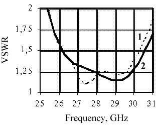 Fig.3.VSWR of microstrip radiator for one (1) and
three (2) dimensional arrays.
Fig.3.VSWR of microstrip radiator for one (1) and
three (2) dimensional arrays.
Input-output and mutual channel coupling is provided at a low enough
level with the help of a cut-off waveguide covering each channel up to
the detector (Fig.1). The microstrip bandpass filters put before detectors
limit channel bandwidth to 4 GHz in agreement with the input radiator bandwidth.
A communal input channel calibration is produced through a special loaded
50 Ohm microstrip line (fig.4) connected with a loaded LMA-422 which
is used as a noise oscillator in the same frequency range. Mutual
coupling of the microstrip line with radiators is provided at -40 dB level.

Fig.4.The loaded microstrip line for communal channel
calibration
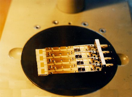
Super low noise HP Schottky square low detectors complete VHF parts
of array. Low noise high precision AD FET monolithic operational amplifiers
are applied in the wideband multi-channel back-end. 4 element sub-array
prototype is shown in Fig.5.
Fig.5. 4 element MMIC sub-array prototype at 26-30 GHz.
Beam patterns of a microstrip radiator in the one dimensional
8 element array (Fig. 6) give us good enough agreement with theory.
 Fig.6. Power beam pattern of a
single microstrip radiator (5.9x3.4 mm) in 8 element array
in H-plane
Fig.6. Power beam pattern of a
single microstrip radiator (5.9x3.4 mm) in 8 element array
in H-plane
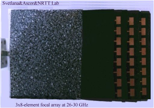
Beam patterns of a microstrip radiator in a 3x8-element array
prototype at 26-30 GHz(Fig.8 a) measured in HUT anechoic chamber
are close to expected(Fig.7.). Fig.8 b. shows the measurement process.
 Fig 7. Power beam patterns of radiating element of
3x8 element array measured in HUT anechoic chamber.
Fig 7. Power beam patterns of radiating element of
3x8 element array measured in HUT anechoic chamber.
 (a)
(a)

(b)
Fig.8. 3x8 element array prototype at 26-30 GHz(a), beam
pattern measurements in HUT anechoic chamber (b).
The measured system temperature of the 8-element MMIC sub-array prototype
is 300 K. We expect 10-15 mK sensitivity per second in a channel in the
"total power" receiving mode. To reduce 1/F noise and deltaG/G
contribution into sensitivity we are testing now a modified radiometric
"total power" scheme with a monochromatic "compensating" signal that can
give us a factor 2-3 in sensitivity. Gann oscillator at 28 GHz with relative
amplitude instability of 4x10⁻⁶ per second has been manufactured
and tested for this aim.
Calculations show (Fig.10,11) that up to 70 7x8 element feed sub-arrays
may be installed along the focal plane of the largest RATAN-600 secondary
mirror N5 (Fig.9 a) so that a total number of RATAN-600 beams can
exceed 3000 (Fig 11 c).
 (a)
(a)
 (b)
(b)
Fig.9.The largest secondary mirror N5 of
RATAN-600(a),
a focal plane of the secondary mirror N1 with single
receivers at present (b).
Really, in some observation modes an aberrationless zone
along the focal plane may exceed 3 m (Fig.10.) for the largest RATAN-600
secondary mirror (12 m size).
 Fig. 10. RATAN-600 power aberration curves along
the focal plane
Fig. 10. RATAN-600 power aberration curves along
the focal plane
C-Zenith mode (H=90 deg.) with 400 meter aperture.
B-Zenith mode (H=89 deg.) with 400 meter aperture.
D-Radio-Schmidt mode with 100 meter aperture (H=45 deg).
|
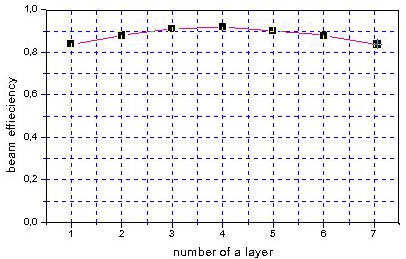
Cross direction of the focal plane is also available for the tight packed
feed array. Vertical RATAN-600 beam patterns for a 7x8 element flat
focal array are shown in Fig.5 a. A tight packed "terraced" array
gives us even a less (8-16%) fall of power beam efficiency than a flat
array(0-24%) (Fig.5 a,b). Optimal two- dimensional array architecture
for RATAN-600 focal plane is presented in Fig.11 c.
 (a)
(a)
 (b)
(b)
 (c)
(c)
Fig. 11. a) Vertical power beam patterns of RATAN-600
with 7x8 element flat focal array, fall of beam efficiency for radiators
of different array levels in "terraced" construction in comparison with
single horn placed at focal line. b) an optimal array which
can be placed in the focal plane
In the Radio-Schmidt mode RATAN-600 can track cosmic sources with
an unmovable main mirror and a focal array during one hour. The RATAN-600
beam patterns in Radio-Schmidt mode for different elevation angles
and azimuths
of cosmic source are shown
in Fig.12. For a shortened aperture we can use this mode up to 10 mm wavelength.

Fig12.RATAN-600 power beam patterns in Radio-Schmidt
mode for different elevation angles and half an hour cosmic source tracking
The described array technology can be used at RATAN-600 for different
radio astronomy applications. It can give us new possibilities to study
CMBA at sub-degree scales with high integrated sensitivity
in a wide field of view (Parijskij et al, 1997 ). The search of Synaev-Zeldovich
effect at RATAN-600 (Parijskij et al., 1997) is among other possible
applications. Using focal arrays we can study quick-variable cosmic objects
like pulsars or Sun as well.
This work was partially supported by INTAS 97-1192.
S.Weinreb. Noise Temperature Estimations for a Next Generation Very
Large Microwave Array. Square-Kilometer Array Workshop, Green Bank, WV,
October, 1998
V.B.Khaikin, E.K.Majorova,
R.G.Shifman, M.D.Parnes, V.A.Dobrov, V.O.Guzevich. MMIC Solution for Multi-pixel
Reception in RATAN-600 Aberrationless Focal Zone. Proceedings of 2-nd
ESA Workshop on Millimetre Wave Technology and Applications, Espoo,
May 1998.
Yu.Parijskij. RATAN-600 Word's Biggest Reflector at the Cross Road.
IEEE AP Magazine, v.35, N.4, pp.7-12,1993.
Yu.Parijskij, G.Pinchuk, E.Majorova, D.Shannikov. Multi-beam Operational
Mode at RATAN-600 Radio Telescope. IEEE AP Magazine, v.35,
N.5, pp.18-27, 1993.
Yu.Parijskij et
al. "Dark Ages" of the Universe. Proceed. of International School of
Astrophysics" D.CHALONE", 1997.