Next: Filters and bandpasses Up: Observations with a low Previous: Aims Contents
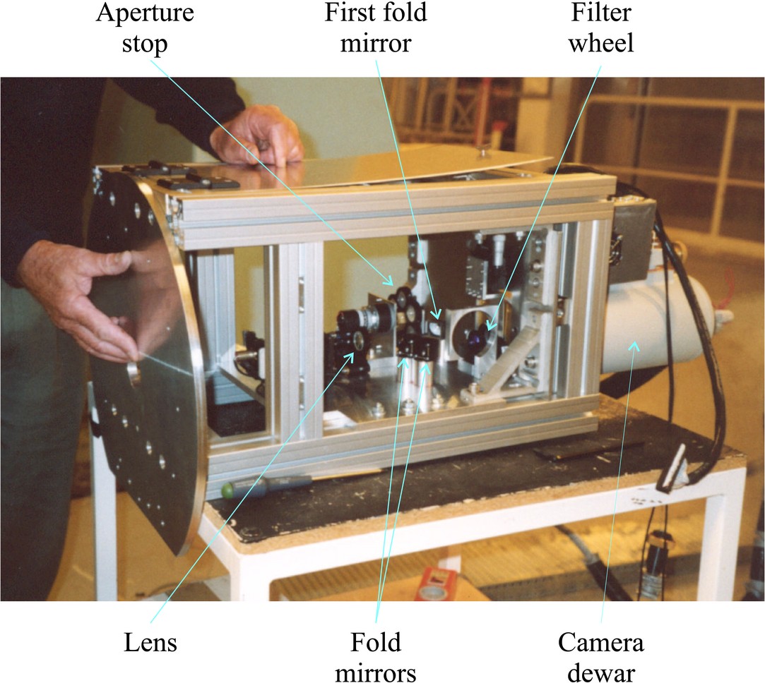
For each of the runs the camera was shipped from Cambridge along with a supporting frame for fitting at the Cassegrain focus of the NOT. The optics and mechanics of the instrument were designed by John Baldwin, Craig Mackay and Donald Wilson. The frame used for the run in 2003 can be seen during assembly in Figure 5.1. The metal plate being attached on the left-hand side of the instrument is the mechanical interface to the telescope, while the camera dewar can be seen on the right-hand side of the frame.
 |
In order to measure the isoplanatic angle it was necessary to
undertake simultaneous imaging observations of widely separated
stars. The limited dimensions of the L3Vision CCDs did not give a
sufficiently wide field of view for this, given the requirements on
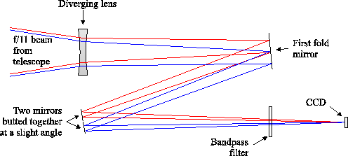
pixel sampling with the Lucky Exposures technique, so a special optical
arrangement was designed by John Baldwin to superimpose two fields of
view on the detector. This allowed stars separated by up to ![]()
![]() to be observed simultaneously. A sketch of the optical layout used for
observations in July 2001 and July 2002 is shown in
Figure 5.2. The light path to the detector was folded into a
``Z'' shape. The second fold mirror actually consisted of two flat
mirrors butted together at a slight angle, allowing two patches of sky
(typically
to be observed simultaneously. A sketch of the optical layout used for
observations in July 2001 and July 2002 is shown in
Figure 5.2. The light path to the detector was folded into a
``Z'' shape. The second fold mirror actually consisted of two flat
mirrors butted together at a slight angle, allowing two patches of sky
(typically ![]()
![]() apart) to be superimposed on the
detector. In the figure, rays from two points on the sky which are
superimposed on the detector are shown in red and blue. The second light
path to the detector was blocked for observations of crowded fields to
prevent confusion and to reduce the sky background contribution.
apart) to be superimposed on the
detector. In the figure, rays from two points on the sky which are
superimposed on the detector are shown in red and blue. The second light
path to the detector was blocked for observations of crowded fields to
prevent confusion and to reduce the sky background contribution.
 |
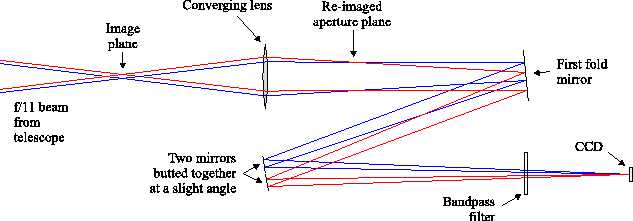
For the observing run in June/July 2003, a converging lens achromat was used after the Cassegrain focus as shown in Figure 5.3, providing a re-imaged aperture plane. The light path after this lens was folded in a similar way to the observations in 2001 and 2002, and also allowed two fields on the sky to be superimposed.
 |
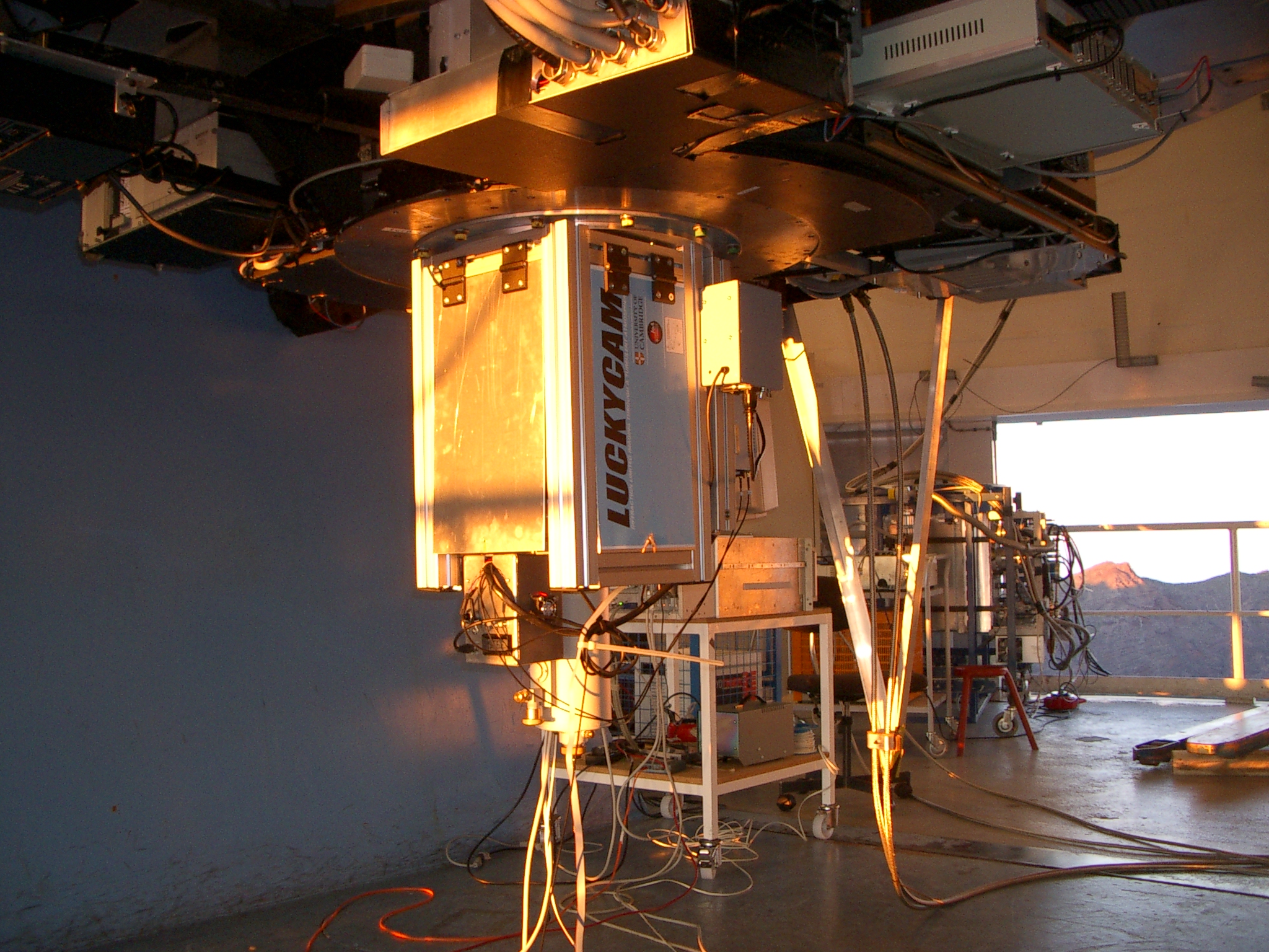
The instrument design in 2003 allowed the telescope aperture to be stopped down in the re-imaged aperture plane using a remotely controlled mechanical system. Filter changes were performed manually during the night using a rotating filter wheel. Figure 5.4 shows the fully assembled ``Luckycam'' instrument mounted at the Cassegrain focus of the NOT.
 |
The camera used was one designed by Craig Mackay to run L3Vision
detectors. The CCD was held in a liquid nitrogen dewar which was cooled
to between ![]()
![]() and
and ![]()
![]() to minimise the dark current. An
Astrocam 4100 controller was used to read out the CCD, with additional
electronics providing the high voltage clock signal for the
multiplication register. The CCDs were read out at frame rates between
to minimise the dark current. An
Astrocam 4100 controller was used to read out the CCD, with additional
electronics providing the high voltage clock signal for the
multiplication register. The CCDs were read out at frame rates between
![]()
![]() and
and ![]()
![]() , using sub-array readout where necessary to
reduce the readout time.
, using sub-array readout where necessary to
reduce the readout time.