Main
· Science
· Instrument
· Backend
· Channelizer
· Design
· Software
· Transmission line
· Power Splitter
· Bandpass Filter
· Mixer
» Amplifier
· Jumper
· SMA Connector
· Enclosure
· Fabrication
· Performance
· Future Revisions
· Correlator
· Receiver
· Optics
· Data Acquisition
· Local Oscillator
· Base
· Analysis
· Results
· Publications
· Team
The channelizer currently uses the Minicircuits ERA-5SM (catalog) amplifier, although it is likely that we will switch to the HP INA-02186 (data sheet). Both are of the very popular 4-pin surface mount button package. The amplifier itself is very small. It's the support electronics that take up most of the space. It's important to note that the amplifier is temperature sensitive. Because of the variation of gain with temperature, we may have to servo the channelizer.
fig 1 Circuit diagram for ERA amplifiers. Taken from Minicircuits App Note
Both sides of the amplifier are DC blocked. This is done on the input because these amplifiers in general cannot handle DC. It is blocked on the output because the power is supplied via the output port. These amps are in general current biased, so there most be a resistor to limit the current. There is also an optional inductor on the power supply to block rf power going into the power supply.
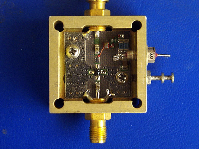
fig 2 The inspiration for the amplifier layout comes from the eval board supplied by Minicircuits. All components are surface mount except the inductor, which was wire bonded.
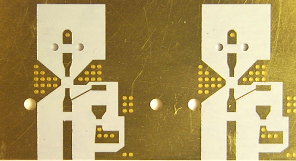
fig 3 layout for amplifiers
The layout for the amplifiers is slightly more complicated than the layout for the mixers. The signal comes in from a via then is decoupled at the capacitor. The trace takes a slight taper before the input pin of the amp. The ground pins of the amp are connected to pads that are heavily connected to ground by the grid of vias. This is important for both microwave and heat reasons. The power for the amp also comes in from underneath the board. We accomplish this with a sectioned ground plane. There is a thin strip on the bottom layer of the board that is electrically isolated from ground. Vias then bring power to the top layer.
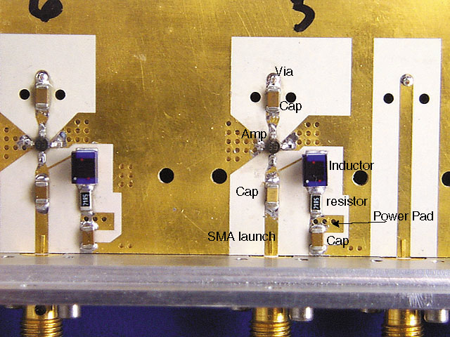
fig 4 Amplifier section with all components mounted.
The finished amplifier section. The largest chip is the inductor. The sma connector as shown above is not soldered, we sill eventually solder it when we are convinced that the board will not come out of the enclosure.