Active correction of wavefront perturbations introduced by the
atmosphere is known as adaptive optics. The simplest form of adaptive
optics system is a mechanical tip-tilt corrector which removes the
average gradient in wavefront phase across a telescope aperture. With
this level of correction, diffraction-limited long exposure imaging
can only be performed for aperture diameters up to 3.4 diameter
(Noll, 1976). To obtain diffraction-limited images from larger
telescopes, the shape of the perturbations in the wavefront across the
telescope aperture must be measured and actively corrected. Deformable
mirrors in a re-imaged pupil-plane are most often used to introduce
additional optical path which corrects the perturbations introduced by
the atmosphere as shown schematically in
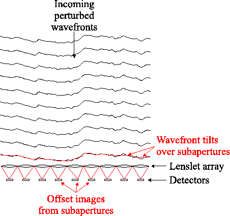
Figure 1.8. One of the simplest systems for
measuring the shape of the wavefront is a Shack-Hartmann array (see
Figure 1.9). This consists of a series of
subapertures typically of
diameter
(Noll, 1976). To obtain diffraction-limited images from larger
telescopes, the shape of the perturbations in the wavefront across the
telescope aperture must be measured and actively corrected. Deformable
mirrors in a re-imaged pupil-plane are most often used to introduce
additional optical path which corrects the perturbations introduced by
the atmosphere as shown schematically in
Figure 1.8. One of the simplest systems for
measuring the shape of the wavefront is a Shack-Hartmann array (see
Figure 1.9). This consists of a series of
subapertures typically of  diameter, positioned across a
telescope pupil-plane. The wavefront sensor accepts light from the
reference star, while light from the science object (or light at a
science imaging wavelength) is directed to a separate imaging
camera. Each subaperture contains a focusing element which generates
an image of the reference source, and the position offset of these
images is used to calculate the mean gradient of the wavefront phase
over each subaperture. The gradient measurements can then be pieced
together to provide a model for the shape of the wavefront
perturbations. This model is then fed into the wavefront corrector. In
order to accurately correct the rapidly fluctuating atmosphere using a
stable servo-feedback loop, the process must typically be repeated ten
times per atmospheric coherence time (see
e.g. Hardy (1998); Karr (1991)). The atmospheric coherence time itself is
usually found to be shorter for measurements through small
subapertures than for imaging through the full telescope aperture, as
will be discussed further in Chapter 2 (see also
Roddier et al. (1982a)).
diameter, positioned across a
telescope pupil-plane. The wavefront sensor accepts light from the
reference star, while light from the science object (or light at a
science imaging wavelength) is directed to a separate imaging
camera. Each subaperture contains a focusing element which generates
an image of the reference source, and the position offset of these
images is used to calculate the mean gradient of the wavefront phase
over each subaperture. The gradient measurements can then be pieced
together to provide a model for the shape of the wavefront
perturbations. This model is then fed into the wavefront corrector. In
order to accurately correct the rapidly fluctuating atmosphere using a
stable servo-feedback loop, the process must typically be repeated ten
times per atmospheric coherence time (see
e.g. Hardy (1998); Karr (1991)). The atmospheric coherence time itself is
usually found to be shorter for measurements through small
subapertures than for imaging through the full telescope aperture, as
will be discussed further in Chapter 2 (see also
Roddier et al. (1982a)).
Figure 1.8:
Adaptive optics correction of atmospherically perturbed
wavefronts using a deformable mirror.
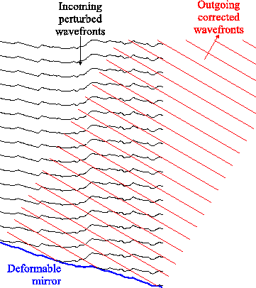 |
Figure 1.9:
Schematic of a Shack-Hartmann wavefront sensor positioned in
a telescope pupil-plane. An array of lenslets act as subapertures, and
the position of the image centroid measured using each subaperture is
used to calculate the wavefront tilt over this subaperture. These
wavefront tilts are then used to construct a model of the wavefront
shape over the full telescope aperture.
 |
Bob Tubbs
2003-11-14